Remote body contact free closed loop motion control
Optic motion detection and motion control system
Picture 1:Event [112], two observers and machine motion control system
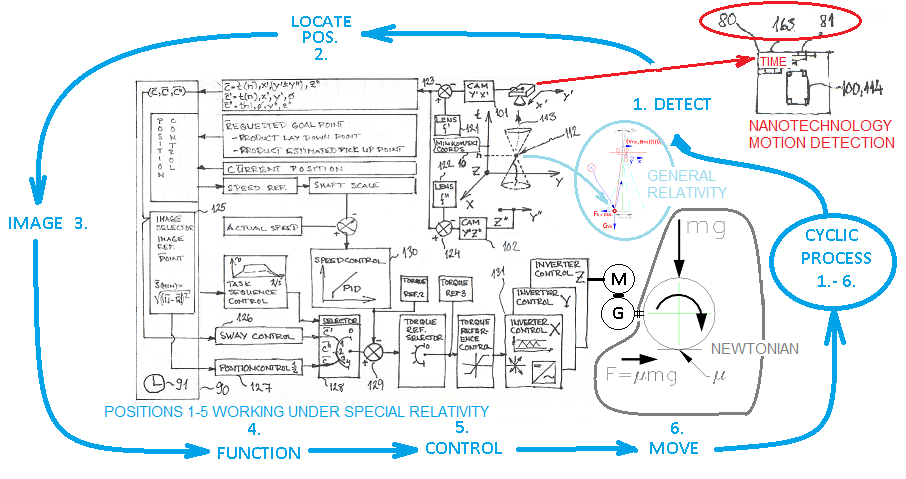
Closed loop motion control from event (112) to motion control 131 and motors Newtonian friction force F=μmgBy looping control cycle, Newtonian gravity acceleration dependent contant 'g' in force F will ignored. Hole process loop 1.-5. measure and control motion under rules of special relativity. Motion control will only improve when prosess calculation capacity will improve. Calculation capacity is cheap resource compared to huge material flow and the energy needed to lift, transfered and put down it. Furthermore, optic machine vision technology provide also other 'free' benefits which improve safety and reliability like visual view. We could drive system more in the edge, when we have friction based motion drive. When system calculated motion speed will not achieved, motion control system internal acceleration and deceleration may be readjusted. Colored area show the scope of technology to be used. Relativity theories cover all other but friction between wheel and track. When control is looping the use of NEWTONIAN gravity theory is not used for motion control. Newtonian tehnology will used for material strength dimensioning on which relativity do not provide solutions. When motion detection will be done by image data and accurate time datafusion. E.g. with 'standard' 100ns accuracy, motion detection pointo-to-point distance resolution accuracy (x(1)-x(0)) fullfill NANOTECHNOLOGY technology limits. Cyclic control process items 1.- 6. time is dependent on calculation capacity. When cycles run item steps (1.-6.) inside the time scope of interest (less than 100ms and TIMER resolution 100ns), the sway motion controllability will be the most efficient. Descriptions: NEWTONIAN = area that neither special relativity nor general relativity do not cover. 80=image data captured,81=individual pixel map, 100,114=object under gravity and acceleration forcies, 163=accurate time when observer receive image, 101=observer 1 (camera), 102=observer 2 (camera), 112=light reflecting event on objects surface, 113=light waves (info about the event), 121,122=zoom cam lens, 123,124=zoom lens position control, etc. In item 1. light waves (113) carry sway position information with several parallel light waves where as control system items 2.-5. transfer data in a form of serial data. The serial data transfer speed is always slower than the parallel data transfer speed and therefore captured image (80) with a time stamp (163) solve several problems with data transfer delays. |
The speed of light is fastest method to transfer information. Light travels always with the same speed compared to any observer dispite of the observers own speed.
|
Image and time datafusion
If accurate time like prosessor timer will improve control accuracy. Time and image datafusion reduce the need of image transfer speed. Several CPU cores can work paralell under their timers syncronized to each others. |
Picture 2:Motion control to improve material handling
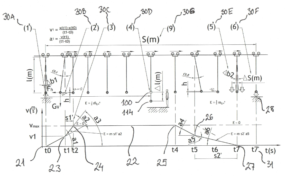
Our proach towards tomorrows global more effective material transfer When starting materia transfer on earth or space, materia internal inertia can not be avoided. On earth it is evitable that a body stays behind when we start motion. We can try to prevent this sway movement with different kind of mechanical anti-sway and reposition systems which we will not here describe. Control sway motion control take advantage of this free sway motion and weak gravity force. Picture 2 describe different motion related situations that we can control better with closed loop motion control. Other observers and remote body motion detection systems may exits but but we hope that this demonstartion will interest you and we could come and tell about it more. This technology study is done to ensure better wireless and TCP/IP package image transfer. |
Picture 3:Minkowski's co-ordinatesystem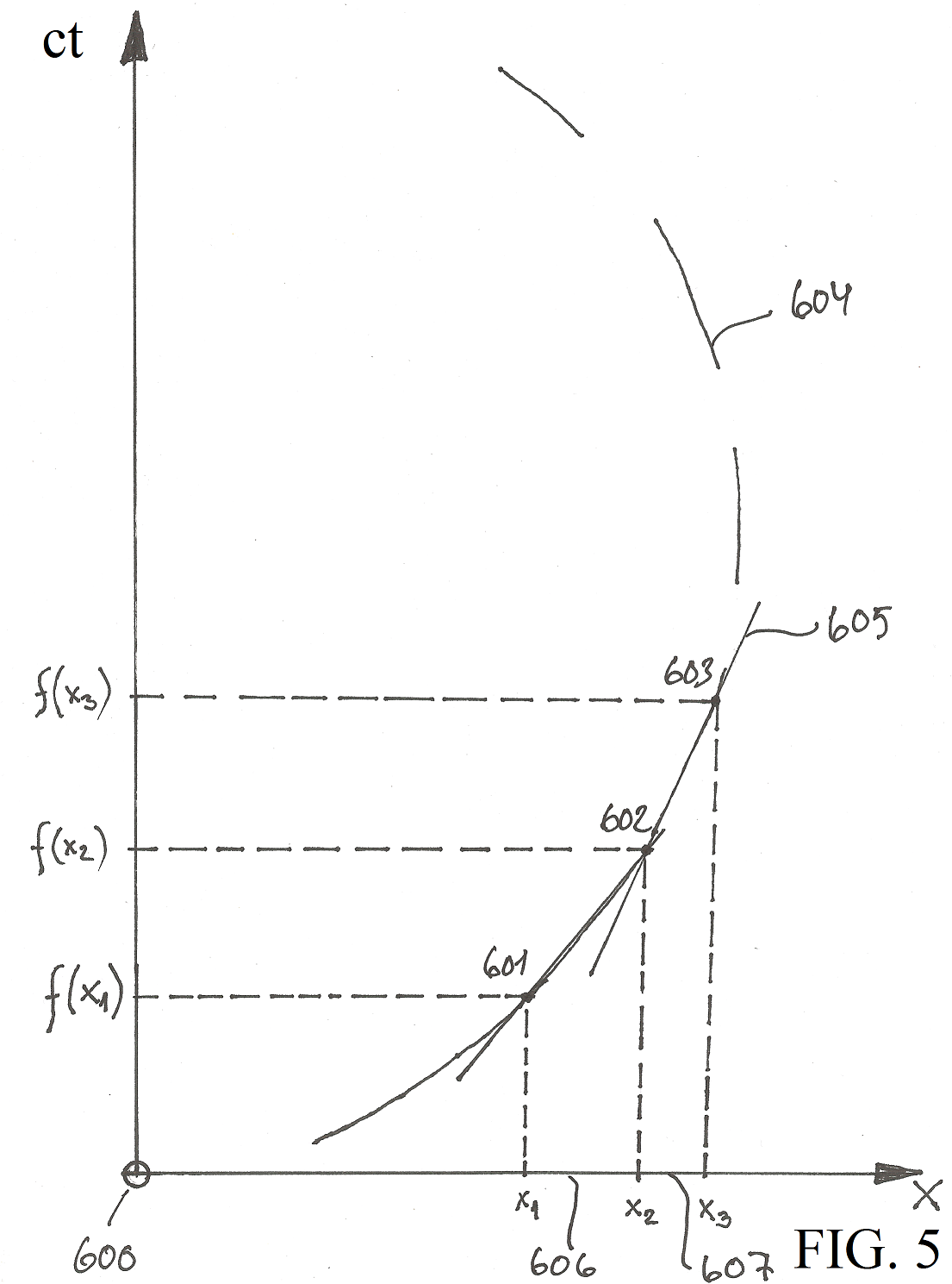
Our proach towards tomorrows accurate inverter motion control technology Inverter control motors by adjusting its electromanetic fields. This force is much stronger as gravitation force. Actually force between two electrons is 10^42 times greater [20] than gravitation force. Gravitation force efects to all particles of which has a mass. So to control motion so that we fix gravitation related forcies and errors require to use accurate co-ordinate system. For that purpose special relativity has Minkowski's co-ordinate system. The use of that to detect gravitation is accurate, simple to understand and use. Especially Minkowski co-ordinate system is a perfect model for future inverter control technology. Descriptions: Minkowski co-ordinate system is the base of relativity and it states accurately the incident (112), light (or any electromagnetic radiation) reflecting time and place for any observer even if observers move. 600=observer's own 3D co-ordinatesytem (e.g. X-Y-Z), object light reflecting detection points 601-602-603 in time order [ct], two measurement points and time determ speed (601-602 and 602-603), three points give us acceleration (601-602-603). Detected X-axis positions for this observer (e.g. 101) are: x1, x2 and x3. Accurate closed loop product and place position detection system is oppertunity!Closed loop sway motion control is a must! Thank you for your interest! |